When working with robot simulations in ROS (Robot Operating System), there are a few important things to understand: XACRO files, transformations, and how odometry is created. Let’s break them down in a simple way.
What is a XACRO File?
A XACRO file is a way to write robot models using XML. It stands for XML Macro. Instead of writing a long and repetitive robot description, XACRO helps you reuse and organize your code better.
You create a .xacro file just like a .urdf (Universal Robot Description Format) file. Which is used to tell the system about your ROBOT like what is the the physical dimension plus using it to visual it.
What is Important in a XACRO File?
-> Links and joints: These define the robot’s structure and how parts are connected.
-> Macros: Let you reuse blocks of code for repeating parts.
-> Parameters: Help change values without editing everywhere.
-> Optional features: You can add sensors, cameras, or extra parts only when needed, using conditional tags.
1. Links and Joints
In a robot, links represent physical parts (like the body, wheels, arms), and joints connect these links, defining how they can move relative to each other.
Example:
XML
<link name="base_link">
  <visual>
    <geometry>
      <box size="0.5 0.3 0.1"/>  <!-- A box shape with length, width, height -->
    </geometry>
    <material name="blue"/>     <!-- Optional: visual color/material -->
  </visual>
</link>

<link name="wheel_left"/>
<joint name="joint_left_wheel" type="continuous">
  <parent link="base_link"/>
  <child link="wheel_left"/>
  <origin xyz="-0.2 0.2 0"/>
  <axis xyz="0 0 1"/>
</joint>
Explanation:
- The <link> tag defines a single part of the robot. In this case, base_link is the robot’s main body.
- visual shows how it looks in simulation.
- geometry defines the shape and size (here, a box).
- A second link wheel_left is created without details for simplicity.
- A <joint> connects base_link and wheel_left, and its type continuous means the wheel can rotate infinitely (used for wheels or motors).
- origin sets the position of the wheel relative to the base.
- axis defines the direction the joint moves or rotates in (Z-axis in this case).
2. Macros Reusing Code Blocks
Macros in XACRO allow you to write a piece of code once and reuse it with different values, making the file cleaner and more maintainable.
Example:
<xacro:macro name="wheel" params="name x y">
  <link name="${name}"/>
  <joint name="joint_${name}" type="continuous">
    <parent link="base_link"/>
    <child link="${name}"/>
    <origin xyz="${x} ${y} 0"/>
    <axis xyz="0 0 1"/>
  </joint>

</xacro:macro>
<!-- Use the macro twice with different names and positions -->
<xacro:wheel name="left_wheel" x="-0.2" y="0.2"/>
<xacro:wheel name="right_wheel" x="-0.2" y="-0.2"/>
Explanation:
- <xacro:macro> defines a reusable block named wheel.
- params lists parameters passed when calling the macro (like name and coordinates).
- Inside the macro, the ${…} syntax is used to insert values dynamically.
- Later, the macro is called twice to create two wheels with different names and positions.
- This reduces duplication and helps when you want to change all wheels at once.
3. Parameters Making Values Configurable
Parameters allow you to define values (like dimensions) at the beginning of your file and reuse them throughout. This makes tuning and updates much easier.
Example:
<xacro:property name="wheel_radius" value="0.1"/>
<xacro:property name="wheel_width" value="0.05"/>

<link name="wheel_example">
  <visual>
    <geometry>
      <cylinder radius="${wheel_radius}" length="${wheel_width}"/>
    </geometry>
  </visual>
</link>
Explanation:
- <xacro:property> declares a named value (like a variable).
- wheel_radius and wheel_width are used in the cylinder geometry.
- If you want to change the wheel size later, you only need to update the value at the top of the file.
- This is especially helpful when the same value is used in multiple places.
4. Optional Features Conditional Inclusion
Sometimes, you may want to include features only when needed (for example, a camera for certain models). XACRO supports conditional logic using <xacro:if>.
Example:
<xacro:property name="add_camera" value="true"/>

<xacro:if value="${add_camera}">
  <link name="camera_link">
    <visual>
      <geometry>
        <box size="0.1 0.1 0.1"/>
      </geometry>
    </visual>
  </link>
</xacro:if>
Explanation:
- add_camera is a boolean property (true or false).
- <xacro:if> checks if the value is true before including the block.
- If add_camera is set to false, this camera link will not be added to the robot model.
- This is useful for making robot models more modular and flexible.
What Are Transformations in ROS?
In robotics, Transformations (TF) are used to describe how different parts of the robot are positioned and oriented relative to one another. ROS provides a powerful system called tf that helps keep track of these transformations over time.
Imagine a robot with multiple parts: a base, two wheels, a camera, and an arm. Each part has its own coordinate frame a 3D reference point that defines its position and orientation in space. ROS uses the tf library to:
- Define how each part is connected (e.g., the camera is 10 cm above the base).
- Continuously update the positions when the robot moves or turns.
- Let other systems (like visualization or control algorithms) understand where each part is at any moment.
This system is like the skeleton of the robot’s perception it connects everything together in one consistent structure.
Example:
If the robot moves forward by 1 meter, the base link’s position changes. All parts (like the wheels or sensors) must also update their positions relative to the world. TF handles this automatically by tracking the transformation from:
- odom -> base_link
- base_link -> wheel_left
- base_link -> camera_link
and so on.
FULL XACRO
<?xml version='1.0'?>

<robot name="atom" xmlns:xacro="http://www.ros.org/wiki/xacro">
	<xacro:property name="robot_name" value="atom" />
	<xacro:property name="robot_chassis_mass" value="15"/>
	<xacro:property name="robot_chassis_length" value="0.2"/>
	<xacro:property name="robot_chassis_radius" value="0.25"/>
	<xacro:property name="robot_caster_wheel_radius" value="0.05"/>
	<xacro:property name="robot_caster_wheel_radius_collision" value="0.0499"/>

	<xacro:property name="robot_wheel_mass" value="5"/>
	<xacro:property name="robot_wheel_length" value="0.05"/>
	<xacro:property name="robot_wheel_radius" value="0.1"/>

	<xacro:property name="camera_mass" value="0.1"/>
	<xacro:property name="hokoyu_mass" value="1e-5"/>

	<!-- Root link -->
	<link name="base_link" />

	<!-- Base link to chassis -->
	<joint name="base_link_to_chassis" type="fixed">
		<origin xyz="0 0 0" rpy="0 0 0" />
		<parent link="base_link"/>
		<child link="chassis" />
	</joint>

	<!-- Make Chassis of Bot -->
	<link name="chassis">
		<pose>0 0 0.1 0 0 0</pose>

		<inertial>
			<mass value="${robot_chassis_mass}"/>
      		<origin xyz="0.0 0 0" rpy=" 0 0 0"/>
      		<inertia
      			ixx="0.147116667" ixy="0" ixz="0"
      			iyy="0.334951167" iyz="0"
      			izz="0.3978345"
      		/>
		</inertial>

		<collision name="collision">
			<origin xyz="0 0 0.05" rpy=" 0 0 0"/>
			<geometry>
				<box size="0.5 0.5 0.2"/>
			</geometry>
		</collision>

		<visual name="chassis_visual">
			<origin xyz="0 0 0.05" rpy=" 0 0 0"/>
			<geometry>
				<box size="0.5 0.5 0.2"/>
			</geometry>
		</visual>
	</link>

	<!-- Wheel links (front/back, left/right) -->
	<!-- Right Wheel Back -->
	<link name="right_wheel_back">
		<inertial>
			<mass value="${robot_wheel_mass}"/>
			<origin xyz="0 0 0" rpy="0 1.5707 1.5707"/>
			<inertia ixx="0.1" ixy="0.0" ixz="0.0" iyy="0.1" iyz="0.0" izz="0.1"/>
		</inertial>
		<visual>
			<origin xyz="0 0 0" rpy="0 1.5707 1.5707"/>
			<geometry><cylinder radius="${robot_wheel_radius}" length="${robot_wheel_length}"/></geometry>
			<material name="black">
  			<color rgba="0 0 0 1"/>
			</material>
		</visual>
		<collision>
			<origin xyz="0 0 0" rpy="0 1.5707 1.5707"/>
			<geometry><cylinder radius="${robot_wheel_radius}" length="${robot_wheel_length}"/></geometry>
		</collision>
	</link>

	<!-- Right Wheel Front -->
	<link name="right_wheel_front">
		<inertial>
			<mass value="${robot_wheel_mass}"/>
			<origin xyz="0 0 0" rpy="0 1.5707 1.5707"/>
			<inertia ixx="0.1" ixy="0.0" ixz="0.0" iyy="0.1" iyz="0.0" izz="0.1"/>
		</inertial>
		<visual>
			<origin xyz="0 0 0" rpy="0 1.5707 1.5707"/>
			<geometry><cylinder radius="${robot_wheel_radius}" length="${robot_wheel_length}"/></geometry>
			<material name="black">
  			<color rgba="0 0 0 1"/>
			</material>
		</visual>
		<collision>
			<origin xyz="0 0 0" rpy="0 1.5707 1.5707"/>
			<geometry><cylinder radius="${robot_wheel_radius}" length="${robot_wheel_length}"/></geometry>
		</collision>
	</link>

	<!-- Left Wheel Back -->
	<link name="left_wheel_back">
		<inertial>
			<mass value="${robot_wheel_mass}"/>
			<origin xyz="0 0 0" rpy="0 1.5707 1.5707"/>
			<inertia ixx="0.1" ixy="0.0" ixz="0.0" iyy="0.1" iyz="0.0" izz="0.1"/>
		</inertial>
		<visual>
			<origin xyz="0 0 0" rpy="0 1.5707 1.5707"/>
			<geometry><cylinder radius="${robot_wheel_radius}" length="${robot_wheel_length}"/></geometry>
			<material name="black">
  			<color rgba="0 0 0 1"/>
			</material>
		</visual>
		<collision>
			<origin xyz="0 0 0" rpy="0 1.5707 1.5707"/>
			<geometry><cylinder radius="${robot_wheel_radius}" length="${robot_wheel_length}"/></geometry>
		</collision>
	</link>

	<!-- Left Wheel Front -->
	<link name="left_wheel_front">
		<inertial>
			<mass value="${robot_wheel_mass}"/>
			<origin xyz="0 0 0" rpy="0 1.5707 1.5707"/>
			<inertia ixx="0.1" ixy="0.0" ixz="0.0" iyy="0.1" iyz="0.0" izz="0.1"/>
		</inertial>
		<visual>
			<origin xyz="0 0 0" rpy="0 1.5707 1.5707"/>
			<geometry><cylinder radius="${robot_wheel_radius}" length="${robot_wheel_length}"/></geometry>
			<material name="black">
  			<color rgba="0 0 0 1"/>
			</material>
		</visual>
		<collision>
			<origin xyz="0 0 0" rpy="0 1.5707 1.5707"/>
			<geometry><cylinder radius="${robot_wheel_radius}" length="${robot_wheel_length}"/></geometry>
		</collision>
	</link>

	<!-- Wheel Joints -->
	<joint type="continuous" name="right_wheel_hinge_back">
	    <origin xyz="-0.2 -0.30 0" rpy="0 0 0" />
	    <parent link="chassis"/>
	    <child link="right_wheel_back" />
	    <axis xyz="0 1 0" rpy="0 0 0" />
	    <limit effort="10000" velocity="1000" />
	    <dynamics damping="1.0" friction="1.0" />
	</joint>

	<joint type="continuous" name="right_wheel_hinge_front">
	    <origin xyz="0.2 -0.30 0" rpy="0 0 0" />
	    <parent link="chassis"/>
	    <child link="right_wheel_front" />
	    <axis xyz="0 1 0" rpy="0 0 0" />
	    <limit effort="10000" velocity="1000" />
	    <dynamics damping="1.0" friction="1.0" />
	</joint>

	<joint type="continuous" name="left_wheel_hinge_back">
	    <origin xyz="-0.2 0.30 0" rpy="0 0 0" />
	    <parent link="chassis"/>
	    <child link="left_wheel_back" />
	    <axis xyz="0 1 0" rpy="0 0 0" />
	    <limit effort="10000" velocity="1000" />
	    <dynamics damping="1.0" friction="1.0" />
	</joint>

	<joint type="continuous" name="left_wheel_hinge_front">
	    <origin xyz="0.2 0.30 0" rpy="0 0 0" />
	    <parent link="chassis"/>
	    <child link="left_wheel_front" />
	    <axis xyz="0 1 0" rpy="0 0 0" />
	    <limit effort="10000" velocity="1000" />
	    <dynamics damping="1.0" friction="1.0" />
	</joint>

</robot>
What Is Odometry?
Odometry is the process of estimating the robot’s position and orientation (also called “pose”) based on its movement over time.
Unlike GPS, which provides absolute position, odometry calculates the robot’s position from internal sensors typically from the rotation of wheels (encoders) or velocity inputs.
Odometry tells us:
- How far the robot has moved
- In which direction
- How much it has rotated (turned)
This information is published in ROS as a message (usually of type nav_msgs/Odometry) and is used by localization, mapping, and navigation systems.
Using Encoders with Odometry
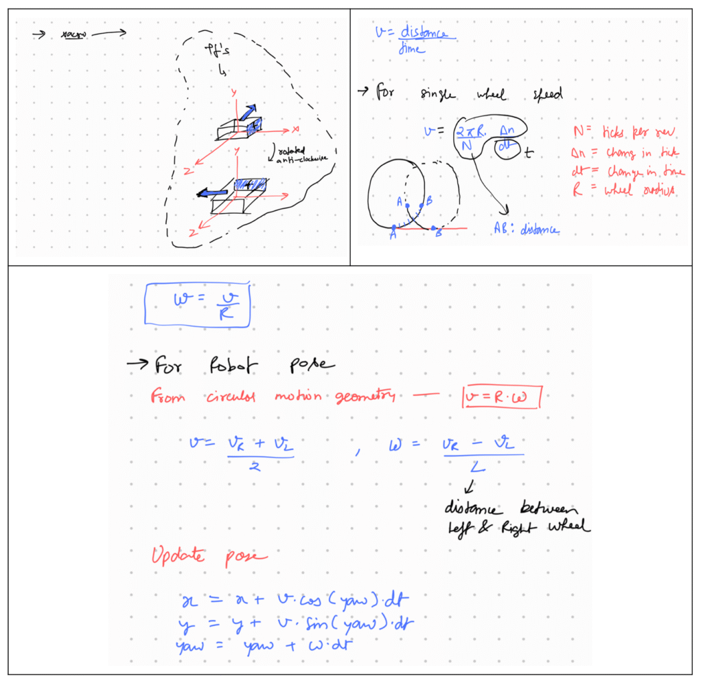
Encoders are sensors that count how much a wheel has rotated. By knowing:
- The wheel radius
- The number of encoder ticks per revolution
- The time difference between measurements
you can compute how much distance the robot has traveled and update its position. This is the basis for real-world odometry.
Example:
If your wheel moves 1 full rotation and the radius is 0.1 m, the distance moved = 2π × 0.1 = 0.628 m. By comparing left and right wheel movements, you can also calculate turning angles.
Simulating Odometry with a Joystick
When working in a simulator like Gazebo, you can mimic robot movement without physical sensors by using input commands from a joystick.
There are two key modes to understand here:
1. IDEAL Case (Simulation or Test Mode)
- You give velocity commands using a joystick.
- These commands are directly used to calculate position.
- TF updates the robot’s pose based on input (not real movement).
- This is useful for testing navigation logic without a real robot.
2. REAL Case (Physical Robot)
- Joystick commands control actual motors.
- The robot physically moves.
- Sensors (like encoders) measure the movement.
- TF updates based on actual sensor data.
In both cases, TF is responsible for showing how the robot moves, but the source of movement data differs:
- Simulated odometry = from command inputs
- Real odometry = from sensor readings
Here is the odometry code I wrote, which is also easy to find anywhere on the internet. I also did some rough calculations by hand to make it easier to understand, and I am sharing them here. It feels good to do some paperwork and draw geometry around your thoughts 🙂
CODE
#!/usr/bin/env python3

import rospy
from sensor_msgs.msg import Joy, JointState
from nav_msgs.msg import Odometry
from geometry_msgs.msg import TransformStamped
import tf
import tf2_ros
import math
import time

class JoystickWheelController:
    def __init__(self):
        rospy.init_node("joystick_wheel_controller", anonymous=True)

        # Publishers
        self.joint_pub = rospy.Publisher("/joint_states", JointState, queue_size=10)
        self.odom_pub = rospy.Publisher("/odom", Odometry, queue_size=10)
        self.tf_broadcaster = tf2_ros.TransformBroadcaster()

        # Subscribers
        rospy.Subscriber("/joy", Joy, self.joy_callback)

        # Parameters
        self.max_vel = rospy.get_param("~max_velocity", 1.0)  # meters/sec
        self.wheel_radius = rospy.get_param("~wheel_radius", 0.1)  # meters
        self.wheel_base = rospy.get_param("~wheel_base", 0.5)  # distance between wheels

        self.encoder_ticks_per_rev = 1000  # fake encoder resolution

        # Robot state
        self.x = 0.0
        self.y = 0.0
        self.yaw = 0.0
        self.last_time = rospy.Time.now()

        self.joint_positions = [0.0, 0.0, 0.0, 0.0]  # [lf, lb, rf, rb]

        # Joystick control
        self.current_linear = 0.0
        self.current_angular = 0.0

        rospy.loginfo("Joystick Wheel Controller initialized.")

    def joy_callback(self, data):
        self.current_linear = data.axes[1] * self.max_vel
        self.current_angular = data.axes[0] * self.max_vel

    def update(self):
        rate = rospy.Rate(50)  # 50 Hz update
        while not rospy.is_shutdown():
            now = rospy.Time.now()
            dt = (now - self.last_time).to_sec()
            self.last_time = now

            v = self.current_linear
            w = self.current_angular

            # Robot position update
            self.x += v * math.cos(self.yaw) * dt
            self.y += v * math.sin(self.yaw) * dt
            self.yaw += w * dt

            # Calculating wheel rotations (rad/s)
            left_speed = v + w * self.wheel_base / 2
            right_speed = v - w * self.wheel_base / 2

            # Increment joint positions
            self.joint_positions[0] += left_speed * dt / self.wheel_radius  # lf
            self.joint_positions[1] += left_speed * dt / self.wheel_radius  # lb
            self.joint_positions[2] += right_speed * dt / self.wheel_radius  # rf
            self.joint_positions[3] += right_speed * dt / self.wheel_radius  # rb

            # Publish joint states
            joint_state = JointState()
            joint_state.header.stamp = now
            joint_state.name = [
                "left_wheel_hinge_front",
                "left_wheel_hinge_back",
                "right_wheel_hinge_front",
                "right_wheel_hinge_back"
            ]
            joint_state.position = self.joint_positions
            self.joint_pub.publish(joint_state)

            # Publish TF
            t = TransformStamped()
            t.header.stamp = now
            t.header.frame_id = "odom"
            t.child_frame_id = "base_link"
            t.transform.translation.x = self.x
            t.transform.translation.y = self.y
            t.transform.translation.z = 0.0
            q = tf.transformations.quaternion_from_euler(0, 0, self.yaw)
            t.transform.rotation.x = q[0]
            t.transform.rotation.y = q[1]
            t.transform.rotation.z = q[2]
            t.transform.rotation.w = q[3]
            self.tf_broadcaster.sendTransform(t)

            # Publish Odometry
            odom = Odometry()
            odom.header.stamp = now
            odom.header.frame_id = "odom"
            odom.child_frame_id = "base_link"
            odom.pose.pose.position.x = self.x
            odom.pose.pose.position.y = self.y
            odom.pose.pose.position.z = 0.0
            odom.pose.pose.orientation.x = q[0]
            odom.pose.pose.orientation.y = q[1]
            odom.pose.pose.orientation.z = q[2]
            odom.pose.pose.orientation.w = q[3]
            odom.twist.twist.linear.x = v
            odom.twist.twist.angular.z = w
            self.odom_pub.publish(odom)

            rate.sleep()


if __name__ == '__main__':
    try:
        controller = JoystickWheelController()
        controller.update()
    except rospy.ROSInterruptException:
        pass
This much should be enough for now, keep learning
Next Step
Instead of sending velocities through your joystick,
Read this article
Get the velocities from there, and directly replace them where you are currently sending velocities via the joystick.
If you are now planning to do it, then congratulations you have already done 99% of the work.
You just need to push yourself a little bit more to complete the remaining 1% congrats.
ALL THE BEST