Introduction
Let me start with why I chose to create this robot-
-> To revise [ Embedded Systems, OpenCV basics, apply some basic concepts, and try a new approach ] .
-> It is going to be fun, yes…
-> I am going to write everything from scratch sounds good, but also a lot of work. Still, after doing it, I am definitely going to feel better.
This is just to test how what I’m thinking will look like in the real world. Although it is not complete yet, it is somewhat there.
So, that is it for the informal intro part… In this doc I am not going to discuss about what I did in embedded systems it is just to log my project only and give few points about it If you want to build the same so very basic working code part I have provided here.
So Let me start with some formal intro like what modern robotics, mobile robot, importance of environment for a robot and few more basic points…
In modern robotics, there are lot of challenges like path finding, navigation, self-driven system and etc. so there are some segments we talk about and focus in some important points.
In this project we are going to use 3rd person perspective… something like that well how that works ?
there is a camera which continuously observes the environment and tracks the robot, and robot in its local system tries to follow semi-autonomy structure it depends what do you want that robot to handle, example – avoiding an obstacle or identifying something or reporting it to server or store it into its database.
What is mobile robotics ?
Robot localization, the ability of a mobile robot to determine its position and orientation within its environment, is crucial for autonomous operation. This process enables robots to navigate, interact with their surroundings, and perform tasks independently.
A variety of sensors can be utilized for robot localization, each providing unique information about the robot’s motion and surroundings. Odometry measures wheel rotations and other motion parameters to
estimate changes in position. Encoders, rotary sensors that measure angular rotation, are often used for wheel rotation to estimate distance travelled. Gyroscopes measure angular rate of rotation, providing information about orientation and changes in orientation. Accelerometers measure acceleration of a body, providing data on speed and direction of travel. GPS provides absolute position outdoors, particularly useful for outdoor robots. LiDAR emits laser beams and measures reflection time to create 3D maps of the environment for position estimation. Cameras extract visual features like corners, edges, and landmarks, matching them to known maps for position estimation.
The choice of sensors depends on the robot’s environment and application. For instance, GPS-denied environments require LiDAR or cameras for localization.
Once sensor data is gathered, localization algorithms are employed to estimate the robot’s position and orientation. Common algorithms include dead reckoning, which estimates position by integrating odometry measurements over time but is susceptible to error accumulation; particle filtering, which utilizes a weighted set of particles to represent possible robot positions, offering better accuracy but higher computational demands; and Kalman filtering, a statistical state estimation algorithm that uses a model of robot motion to estimate position and orientation, balancing accuracy and computational efficiency.
Robot localization presents several challenges, including sensor noise and uncertainty, as all sensors produce noisy and uncertain measurements, which must be considered when estimating position and orientation. Environmental dynamics, as dynamic and unpredictable environments can make it difficult to maintain accurate position estimation over time, and computational complexity, as some localization algorithms are computationally expensive, limiting their use on robots with limited resources.
Despite these challenges, robot localization is an active research area, with researchers developing new sensors and algorithms to improve accuracy and reliability in diverse environments. As these advancements continue, autonomous mobile robots will become increasingly capable of operating in complex and dynamic environments.
This paper is based on robot can be control without using a bit of machine learning models, and at low computation[reference a* requires huge memory], specifically in indoor robotics but with some limitations.
Environment importance for robots
Think of the environment as a stage where robots are the performers, and each robot is like a unique actor built to play a specific role. Just like a stage can be indoors or outdoors, robot environments can vary widely, and each type of environment brings its own challenges. For example, robots designed for indoor use often assume that the surface they operate like the floor is flat and smooth. This is important because many indoor robots rely on such conditions to function correctly and efficiently, based on how they were designed and programmed.
Now, let’s talk about the people behind the scenes engineers who build and program robots. These professionals, known as roboticists, use different tools and techniques to help robots understand and move around their surroundings. In many cases, robots are equipped with special sensors like Lidar, which create detailed maps of the environment and measuring the distance of objects. These maps help robots know where they are and how to navigate without colliding into things.
In this project, I explored a simpler and more like a alternative approach. Instead of using multiple advanced sensors or creating large, detailed maps, I used just a basic camera. The idea was to enable the robot to “see” its environment using this camera alone. Once the camera is fixed in place, it acts as the main frame of reference. As the camera continuously captures frames, the system can detect changes in the environment, such as moving or stationary obstacles. These updates allow the robot to identify potential collisions and adjust its path accordingly.
This method reduces hardware complexity and cost while still allowing effective obstacle detection, demonstrating how even a simple camera can enable smart navigation in robotics while acknowledging that every approach has its own advantages and disadvantages.
| Snip_1 | Snip_2 |
 |  |
Well lets jump to main implementation part, Plus in this version there is no PID but planning to add one in upcoming version.
PID Controller
A PID controller is a control system used to help robots stay on track—literally. It adjusts the robot’s movement based on the difference between where the robot is and where it should be (the desired path). PID stands for:
- P – Proportional
- I – Integral
- D – Derivative
Each part plays a role in correcting the robot’s position or speed:
1. Proportional (P)
This part looks at the current error (how far the robot is from the path) and tries to correct it.
If the error is big, the correction will be stronger.
Think of it as: “How far am I from where I should be right now?”
2. Integral (I)
This part looks at the accumulated error over time.
If the robot keeps drifting off the path slightly, the integral term will add up these small errors and apply a correction.
Think of it as: “Have I been off course for too long?”
3. Derivative (D)
This part checks how fast the error is changing.
If the robot is moving away from the path quickly, the derivative will act early to slow down or reverse that drift.
Think of it as: “Am I starting to go off course too quickly?”
Putting It All Together
The PID controller combines all three parts to calculate a control output, such as adjusting motor speeds. This helps the robot continuously correct its path in a smooth and stable way.
So, when your robot starts to drift away from the line or path, the PID controller will calculate the right amount of adjustment needed to bring it back, ensuring it follows the path as accurately as possible.
Tuning
The most important part of configuring the PID controller is selecting the PID constants. This process is known as “tuning” the PID controller.
Which depends on environment hence it varies with environment.
Main Code functions explanations
The provided function send_serial is responsible for sending control signals to a serial device, likely a microcontroller or motor controller. It takes two parameters: speed and dir. These parameters are interpreted as the desired speed and direction for the controlled device.
def send_serial(speed, dir):
    if destination_x != 1:
        control_string = "<"+str(int(speed)) +","+ str(int(dir))  +","+str(0)  +","+str(0)+">"+"\n"
        print(control_string)
        ser.write(str.encode(control_string))
        time.sleep(0.1)
The function first checks if the destination device is not at the desired position (destination_x != 1). If it’s not, it constructs a control string that contains the speed, direction, and two additional values (possibly for future use). The control string is formatted as <speed>,<direction>,0,0>. The 0 values might be used for other control signals in the future.
The function then prints the constructed control string to the console for debugging purposes. Next, it encodes the control string using str.encode() and writes it to the serial port using ser.write(). This sends the control signal to the connected device.
Finally, the function introduces a delay of 0.1 seconds using time.sleep(0.1). This delay might be necessary to allow the device time to process the received control signal and react accordingly.
def robo_info(situation, signal, angle):
    global E_Developer_I
    global signature
    conc = 86
    font = cv2.FONT_HERSHEY_SIMPLEX
    cv2.putText(img, chr((E_Developer_I)) + " || " + chr(int(signature))+ " || " + chr(conc), (10, 20), font, 0.7, (255, 255, 255), 2)
This updates the info of robot just to get status of robot while debbuging.
def calculate_distance(x1, y1, x2, y2):
    dist_x = x1 - x2
    dist_y = y1 - y2
    length = math.sqrt(dist_x * dist_x + dist_y * dist_y)
    return length
This function calculates the distance between two points in a two-dimensional plane. The function takes four arguments:
x1: The x-coordinate of the first point
y1: The y-coordinate of the first point
x2: The x-coordinate of the second point
y2: The y-coordinate of the second point
The function first calculates the difference in the x-coordinates of the two points (dist_x = x1 – x2). Then, it calculates the difference in the y-coordinates of the two points (dist_y = y1 – y2). Finally, it calculates the length of the hypotenuse of the right triangle formed by the two differences (length = math.sqrt(dist_x * dist_x + dist_y * dist_y)). The function returns the length of the hypotenuse, which is the distance between the two points.
def map_range(value, from_low, from_high, to_low, to_high):
    if value < from_low:
        return to_low
    if value > from_high:
        return to_high
    from_range = from_high - from_low
    to_range = to_high - to_low
    scaled_value = (value - from_low) / from_range
    mapped_value = to_low + (scaled_value * to_range)
    robo_info(0,0,0)

    return mapped_value
The map_range function is designed to linearly map a value from one range to another. It takes five arguments:
value: The value to be mapped.
from_low: The lower bound of the original range.
from_high: The upper bound of the original range.
to_low: The lower bound of the desired range.
to_high: The upper bound of the desired range.
The function first checks if the value falls outside the original range. If it does, it returns the corresponding boundary value (to_low or to_high). If the value is within the original range, it calculates the scaled_value, which represents the relative position of the value within the original range. Finally, it calculates the mapped_value by multiplying the scaled_value by the to_range and adding the to_low.
In essence, the map_range function stretches or compresses the original range to fit within the desired range, ensuring that the mapped value maintains its relative position within the original range.
def control_loop():
    global Red_Robot_x
    global Red_Robot_y
    global destination_x
    global destination_y
    global distance_error_factor
    global distance
    global Twist
    global theta_error
    global min_speed
    global max_speed

    distance = calculate_distance(destination_x, destination_y, Red_Robot_x, Red_Robot_y)
    distance = int(distance/100)

    if 10*distance > distance_error_factor:
        Red_Robot_x, Red_Robot_y, turning,  = detect_robot()
        speed = map_range(10*distance, 10, 100, 40, 45)
        if turning == 0:
            Twist[0] = int(speed)
            Twist[1] = int(turning)
        else:
            Twist[0] = int(0)
            Twist[1] = int(turning)
        # send_serial(Twist[0], Twist[1])
        print(str("in control loop : ")+"Distance: "+str(distance)+", Speed: "+str(Twist[0]) + ", Dir: "+str(Twist[1]))

    else:
        print(str("next goal : ")+"Distance: "+str(distance)+", Speed: "+str(Twist[0]) + ", Dir: "+str(Twist[1]))
        Twist[0] = 0.0
        Twist[1] = 0.0
        # send_serial(Twist[0], Twist[1])
The function control_loop() is responsible for controlling the movement of the Red Robot towards a specified destination. It utilizes sensor data to determine the current position of the robot, calculates the distance to the destination, and adjusts the robot’s speed and direction accordingly.
Global Variables:The function starts by declaring several global variables that it will use to access and modify the robot’s position, destination, and control parameters. These variables include:
Red_Robot_x: The X-coordinate of the Red Robot’s current position
Red_Robot_y: The Y-coordinate of the Red Robot’s current position
destination_x: The X-coordinate of the destination
destination_y: The Y-coordinate of the destination
distance_error_factor: A threshold value for determining when the robot is close enough to the destination
distance: The calculated distance between the robot’s current position and the destination
Twist: A list containing the robot’s linear and angular velocities
theta_error: The angle between the robot’s current orientation and the direction towards the destination
min_speed: The minimum speed the robot can move at
max_speed: The maximum speed the robot can move at
Distance Calculation:The function first calculates the distance between the robot’s current position and the destination using the calculate_distance() function. This distance is then divided by 100 and converted to an integer.
Distance Threshold Check:The function checks if the calculated distance is greater than 10 times the distance_error_factor. If so, it means the robot is still a significant distance from the destination and needs to continue moving.
Robot Detection and Speed Adjustment:If the distance is above the threshold, the function calls the detect_robot() function to update the robot’s current position and determine if it is turning. It then maps the distance to a corresponding speed using the map_range() function. This ensures that the robot moves faster when it is farther from the destination and slows down as it gets closer.
Direction Adjustment:Based on the value of turning, the function sets the linear and angular velocities in the Twist list. If turningis zero, indicating the robot is moving straight, the linear velocity is set to the calculated speed, and the angular velocity is set to zero. Otherwise, if the robot is turning, the linear velocity is set to zero, and the angular velocity is set to the direction of the turn.
Printing and Serial Communication:The function prints a message indicating that it is in the control loop and provides information about the current distance, speed, and direction. It also sends the linear and angular velocities to the robot’s motor controller using the send_serial() function.
Destination Reached:If the distance falls below the distance_error_factor, indicating the robot has reached its destination, the function prints a message indicating that it has reached the next goal and sets both the linear and angular velocities to zero, stopping the robot’s movement.
def detect_robot():
detected_rx=0
detected_ry=0
detected_gx=0
detected_gy=0
mod_destination_angle=0
mod_arrow_angle=0
derivative_constant=1
mapped_value = 0
global min_speed
global max_speed
angle_error_factor = 5
global third_side_angle
global destination_x
global destination_y
global Red_Robot_x
global Red_Robot_y
global theta_error
hsvFrame = cv2.cvtColor(img, cv2.COLOR_BGR2HSV)
red_lower = np.array([0, 141, 206], np.uint8)
red_upper = np.array([8, 224, 255], np.uint8)
red_mask = cv2.inRange(hsvFrame, red_lower, red_upper)
green_lower = np.array([60, 40, 165], np.uint8)
green_upper = np.array([84, 140, 255], np.uint8)
green_mask = cv2.inRange(hsvFrame, green_lower, green_upper)
kernel = np.ones((5, 5), "uint8")
red_mask = cv2.dilate(red_mask, kernel)
res_red = cv2.bitwise_and(img, img, mask = red_mask)
cv2.imshow('red_mask', res_red)
red_contours, hierarchy = cv2.findContours(red_mask, cv2.RETR_TREE, cv2.CHAIN_APPROX_SIMPLE)
green_mask = cv2.dilate(green_mask, kernel)
res_green = cv2.bitwise_and(img, img, mask = green_mask)
cv2.imshow('green_mask', res_green)
green_contours, hierarchy = cv2.findContours(green_mask, cv2.RETR_TREE, cv2.CHAIN_APPROX_SIMPLE)
robo_info(0,0,0)
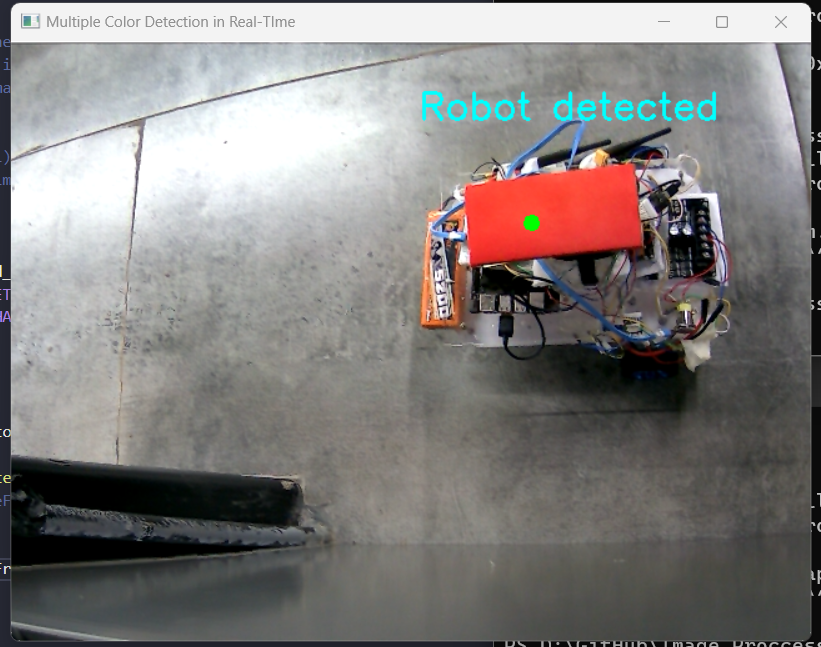
for pic, contour in enumerate(red_contours):
area = cv2.contourArea(contour)
if(area > 1000):
x, y, w, h = cv2.boundingRect(contour)
cv2.putText(img, "Robot detected", (x, y), cv2.FONT_HERSHEY_SIMPLEX, 1.0, (255, 255, 0), thickness=2)
detected_rx = x +(w//2)
detected_ry = y +(h//2)
cv2.circle(img=img, center=(detected_rx, detected_ry), radius=3, color=(0, 255, 0), thickness=5)
for pic, contour in enumerate(green_contours):
area = cv2.contourArea(contour)
if(area > 1000):
x, y, w, h = cv2.boundingRect(contour)
cv2.putText(img, "Direction detected", (x, y), cv2.FONT_HERSHEY_SIMPLEX, 1.0, (255, 255, 0), thickness=2)
detected_gx = x +(w//2)
detected_gy = y +(h//2)
cv2.circle(img=img, center=(detected_gx, detected_gy), radius=3, color=(0, 255, 0), thickness=5)
start_point = (detected_rx, detected_ry)
end_point = (detected_gx, detected_gy)
cv2.arrowedLine(img, start_point, end_point, (255, 0, 0), 3)
qr = abs(detected_gx - detected_rx)
rs = abs(detected_gy - detected_ry)
qs = calculate_distance(detected_gx, detected_gy, detected_rx, detected_ry)
ab = abs(destination_x - detected_rx)
bc = abs(destination_y - detected_ry)
ac = calculate_distance(destination_x, destination_y, Red_Robot_x, Red_Robot_y)
arrow_angles = Calculate_angle(qr, qs, rs)
destination_angles = Calculate_angle(ab, ac, bc)
theta_error = destination_angles[2] - arrow_angles[2]
# Unique Conditions
if detected_gy > Red_Robot_y and detected_gx > Red_Robot_x:
mod_arrow_angle = arrow_angles[2]
elif detected_gy > Red_Robot_y and detected_gx < Red_Robot_x:
mod_arrow_angle = 180 - arrow_angles[2]
elif detected_gy < Red_Robot_y and detected_gx < Red_Robot_x:
mod_arrow_angle = 180 + arrow_angles[2]
elif detected_gy < Red_Robot_y and detected_gx > Red_Robot_x:
mod_arrow_angle = 360 - arrow_angles[2]
else:
print("object is not there")
if destination_y > Red_Robot_y and destination_x > Red_Robot_x:
mod_destination_angle = destination_angles[2]
elif destination_y > Red_Robot_y and destination_x < Red_Robot_x:
mod_destination_angle = 180 - destination_angles[2]
elif destination_y < Red_Robot_y and destination_x < Red_Robot_x:
mod_destination_angle = 180 + destination_angles[2]
elif destination_y < Red_Robot_y and destination_x > Red_Robot_x:
mod_destination_angle = 360 - destination_angles[2]
else:
print("path is not there")
# unique edge cases
if mod_destination_angle>215 and mod_arrow_angle<45:
mod_theta_error = - 1*mod_arrow_angle -1*(360 - mod_destination_angle)
else:
mod_theta_error = mod_destination_angle - mod_arrow_angle
if mod_theta_error > math.pi:
mod_theta_error -= 2*math.pi
elif mod_theta_error < -math.pi:
mod_theta_error += 2*math.pi
if mod_theta_error < -1*angle_error_factor:
mapped_value = map_range(mod_theta_error, -360, -1*angle_error_factor, max_speed, min_speed)
mapped_value = -1*mapped_value
elif mod_theta_error > angle_error_factor:
mapped_value = map_range(mod_theta_error, angle_error_factor, 360, min_speed, max_speed)
else:
mapped_value = 0
turning= derivative_constant*mapped_value
print(str("info: ")
+str(" turning: ")+str((turning))
+str(" mod_destination_angle: ")+str(int(mod_destination_angle))+str(" mod_arrow_angle: ")+str(int(mod_arrow_angle))+str(" mod_theta_error: ")+str(int(mod_theta_error))
)
return detected_rx, detected_ry, turning
 |  |
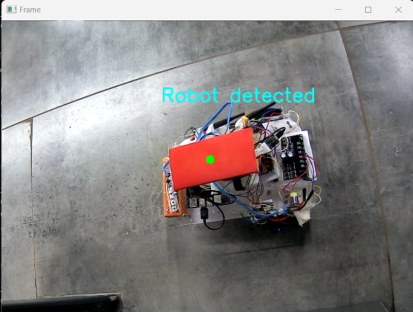
The detect_robot() function is responsible for detecting the presence of robots in the camera image and determining the appropriate turning direction for the robot car. It achieves this by identifying and analyzing red and green contours in the image, which are assumed to represent the robot’s body and arrow, respectively. The function calculates various angles and distances to determine the orientation of the robot and the desired turning direction.
1. Image Processing:The function starts by converting the input image from BGR (Blue, Green, Red) color space to HSV (Hue, Saturation, Value) color space. This is done because HSV is more suitable for color-based segmentation. Next, two masks are created using color thresholding: one for red and one for green. The red mask should capture the robot’s body, while the green mask should capture the arrow. Morphological operations, specifically dilation, are applied to the masks to expand the detected contours and remove any noise or gaps.
2. Contour Detection and Analysis: For each contour in the red mask, the area is calculated. If the area exceeds a certain threshold, it is assumed to represent the robot’s body.The bounding box of the contour is determined, and the center coordinates of the bounding box are stored as the detected robot’s position (detected_rx and detected_ry). Similarly, for each contour in the green mask, the area is calculated. If the area exceeds a certain threshold, it is assumed to represent the arrow. The bounding box of the contour is determined, and the center coordinates of the bounding box are stored as the detected arrow’s position (detected_gx and detected_gy).
3. Angle and Distance Calculations: The distance between the detected robot and the detected arrow is calculated using the Pythagorean theorem. This distance is referred to as qs. The distance between the detected robot and the destination point (the goal location of the robot car) is calculated using the Pythagorean theorem. This distance is referred to as ac. The angle between the robot, the arrow, and the destination point is calculated using the law of cosines. This angle is referred to as destination_angle. The angle between the robot and the arrow is calculated using the law of cosines. This angle is referred to as arrow_angle.
4. Error Calculation and Turn Adjustment: The error between the robot’s current orientation (indicated by the arrow) and the desired orientation (indicated by the destination point) is calculated by subtracting the arrow_angle from the destination_angle. This error is referred to as theta_error. Due to the nature of the angles, special handling is implemented to ensure that the error value remains within the range of 0 to 360 degrees. To determine the appropriate turning direction, the theta_error is compared to a threshold value (angle_error_factor). If the error exceeds the threshold, the robot should turn in the direction that minimizes the error. A mapping function (map_range) is used to convert the theta_error into a turning speed value (mapped_value). The mapping function ensures that larger errors result in larger turning speeds. The final turning speed (turning) is calculated by multiplying the mapped value (mapped_value) by a derivative constant (derivative_constant). This constant determines the responsiveness of the turning behavior.
5. Output and Return Values: The function prints relevant information about the detected positions, angles, and turning speed for debugging purposes.The function returns the detected robot’s position (detected_rx and detected_ry), as well as the calculated turning speed (turning).
The detect_robot() function plays a crucial role in the robot car’s navigation system by providing real-time information about the robot’s surroundings and determining the appropriate turning direction to reach the destination. Its combination of image processing, angle calculations, and error compensation ensures that the robot car can efficiently navigate towards its goal while avoiding obstacles and maintaining a consistent orientation.
def Update_frame():
global Red_Robot_x
global Red_Robot_y
global destination_x
global destination_y
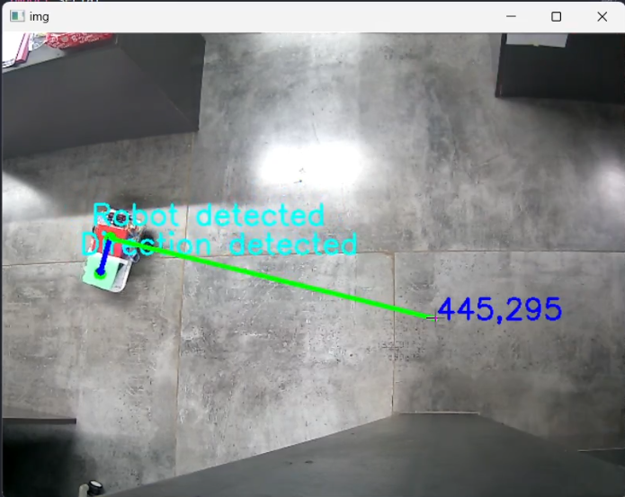
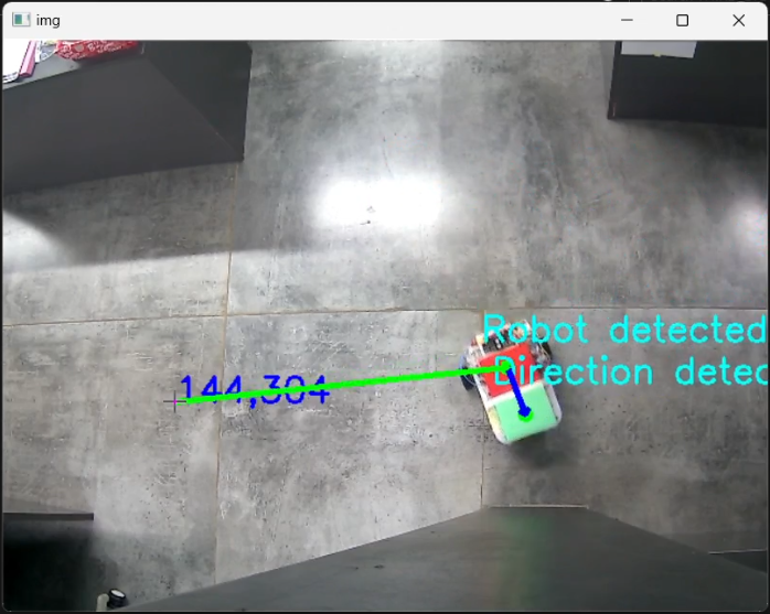
Red_Robot_x, Red_Robot_y , _ = detect_robot()
cv2.putText(img, str(destination_x) + ',' +str(destination_y), (destination_x,destination_y), cv2.FONT_HERSHEY_SIMPLEX, 1, (255, 0, 0), 2)
start_point = (Red_Robot_x, Red_Robot_y)
end_point = (destination_x, destination_y)
color = (0, 255, 0)
thickness = 3
cv2.line(img, start_point, end_point, color, thickness)
The Update_frame() function is designed to periodically update the contents of a video frame with relevant information about the detected red robot and its designated destination. It performs the following actions:
Retrieve Robot’s Position: It calls the detect_robot() function to obtain the current coordinates (Red_Robot_x and Red_Robot_y) of the red robot in the video frame.
Update Robot’s Position: It updates the global variables Red_Robot_x and Red_Robot_y with the retrieved coordinates from detect_robot().
Draw Destination Marker: It draws a text label at the destination coordinates (destination_x, destination_y) using the cv2.putText() function. The text label displays the destination coordinates as a string.
Draw Path Line: It draws a line connecting the robot’s current position (start point) to its designated destination (end point) using the cv2.line() function. The line is drawn with a green color (color parameter) and a thickness of 3 pixels (thickness parameter).
Global Variable Access :Python, global Red_Robot_x, global Red_Robot_y, global destination_x, global destination_y
This section declares four global variables: Red_Robot_x, Red_Robot_y, destination_x, and destination_y. These variables are declared as global to ensure that they can be accessed and modified within the function’s scope.
Robot Position Update: Red_Robot_x, Red_Robot_y , _ = detect_robot()This line calls the detect_robot() function, which is assumed to return a tuple containing the red robot’s coordinates (Red_Robot_x, Red_Robot_y) and possibly other information represented by the _ placeholder. The function’s return values are unpacked into the corresponding global variables.
Destination Marker: cv2.putText(img, str(destination_x) + ',' +str(destination_y), (destination_x,destination_y), cv2.FONT_HERSHEY_SIMPLEX, 1, (255, 0, 0), 2)This line utilizes the cv2.putText() function to draw a text label at the destination coordinates (destination_x, destination_y). The text label displays the destination coordinates as a string formed by concatenating the destination_x and destination_y values with a comma. The font style is set to cv2.FONT_HERSHEY_SIMPLEX, the font scale is set to 1, the text color is set to red ((255, 0, 0)), and the thickness is set to 2 pixels.
Path Line: start_point = (Red_Robot_x, Red_Robot_y)
end_point = (destination_x, destination_y)
color = (0, 255, 0)
thickness = 3
cv2.line(img, start_point, end_point, color, thickness)
This section defines the start point (start_point) as a tuple containing the robot’s current coordinates (Red_Robot_x, Red_Robot_y) and the end point (end_point) as a tuple containing the destination coordinates (destination_x, destination_y). It also defines the line color (color) as green (0, 255, 0) and the line thickness (thickness) as 3 pixels. Finally, it calls the cv2.line() function to draw a line connecting the start point and the end point using the specified color and thickness.
def click_event(event, x, y, flags, params):
    global destination_x
    global destination_y
    if event==cv2.EVENT_RBUTTONDOWN:
        destination_x=x
destination_y=y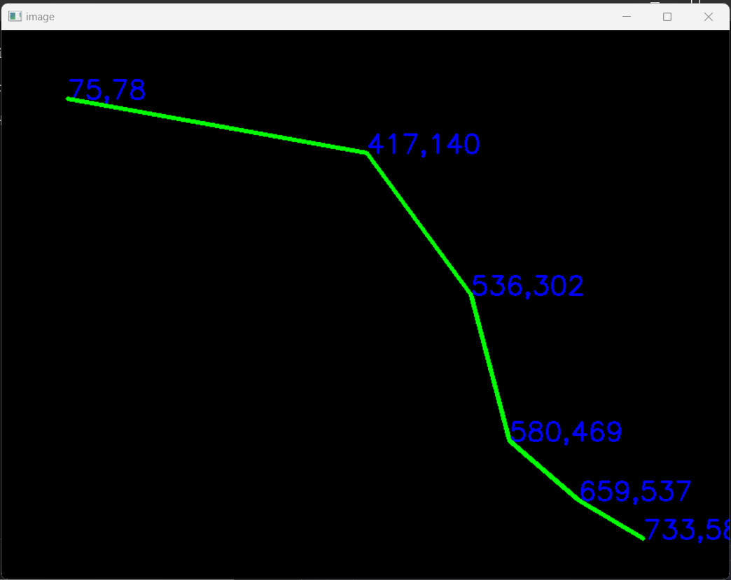 |
The function checks the type of mouse event that occurred. If it is a right mouse button down event (cv2.EVENT_RBUTTONDOWN), then it updates the destination_x and destination_y global variables with the coordinates of the mouse cursor. These global variables can then be used to track the position of the mouse cursor and perform actions accordingly.
declare the destination_x and destination_y variables as global variables. This means that they can be accessed and modified from anywhere within the program, not just within the click_event() function.
These lines update the destination_x and destination_y global variables with the coordinates of the mouse cursor. The x and y parameters passed to the click_event() function contain the X- and Y-coordinates of the mouse cursor, respectively.
In summary, this function is used to track the position of the mouse cursor when a right mouse button down event occurs. The updated destination_x and destination_y global variables can then be used to perform actions accordingly. For example, you could use these variables to draw a line from the current position of the mouse cursor to the point where the user right-clicked.
while True:
    ret, img = cap.read()
    Update_frame()
    cv2.imshow('img', img)
    cv2.setMouseCallback('img', click_event)
    control_loop()
    if cv2.waitKey(10) & 0xFF == ord('q'):
        break

cv2.destroyAllWindows()
The while True: loop ensures continuous execution until the ‘q’ key is pressed. Inside the loop, the following steps occur. This line captures the next frame from the video capture object ‘cap’ and stores the frame data in the ‘img’ variable.
Update_frame() This function updates the internal state based on the captured frame, likely performing operations like object detection or tracking.cv2.imshow(‘img’, img) This line displays the captured frame in a window named ‘img’.
cv2.setMouseCallback(‘img’, click_event) This function registers the click_event callback to handle mouse clicks on the ‘img’ window.
control_loop() This function likely performs additional processing tasks or handles user interactions.
if cv2.waitKey(10) & 0xFF == ord(‘q’) break: This line checks if the ‘q’ key has been pressed. If so, it breaks out of the loop, terminating the program.
The cv2.destroyAllWindows() statement at the end destroys all open windows, ensuring proper cleanup before exiting.
# Code is in development - Dev

import cv2
import math
import numpy as np
import time

debug = 0
destination_x =1
destination_y =1
Red_Robot_x =1
Red_Robot_y =1
distance = 1
third_side_angle = 0
min_speed = 35
E_Developer_I = 68
max_speed = 40
distance_error_factor = 5
Twist = [0, 0]
theta_error = 0
prev_error = 0
control_string = ""
control_string += str(0)+"," + str(0) +","+ str(0) +"," + str(0) + "\n"
speed = 50
signature = 70
ser = 0

cap = cv2.VideoCapture(1)
Only declared variables and imported the necessary libraries.
Full Code:
# Code is in development - Dev

import cv2
import math
import numpy as np
import time

debug = 0
destination_x =1
destination_y =1
Red_Robot_x =1
Red_Robot_y =1
distance = 1
third_side_angle = 0
min_speed = 35
E_Developer_I = 68
max_speed = 40
distance_error_factor = 5
Twist = [0, 0]
theta_error = 0
prev_error = 0
control_string = ""
control_string += str(0)+"," + str(0) +","+ str(0) +"," + str(0) + "\n"
speed = 50
signature = 69
ser = 0

cap = cv2.VideoCapture(1)

def send_serial(speed, dir):
    if destination_x != 1:
        control_string = "<"+str(int(speed)) +","+ str(int(dir))  +","+str(0)  +","+str(0)+">"+"\n"
        print(control_string)
        ser.write(str.encode(control_string))
        time.sleep(0.1)

def robo_info(situation, signal, angle):
    global E_Developer_I
    global signature
    conc = 86
    font = cv2.FONT_HERSHEY_SIMPLEX
    cv2.putText(img, chr((E_Developer_I)) + " || " + chr(int(signature))+ " || " + chr(conc), (10, 20), font, 0.7, (255, 255, 255), 2)

def calculate_distance(x1, y1, x2, y2):
    dist_x = x1 - x2
    dist_y = y1 - y2
    length = math.sqrt(dist_x * dist_x + dist_y * dist_y)
    return length

def map_range(value, from_low, from_high, to_low, to_high):
    if value < from_low:
        return to_low
    if value > from_high:
        return to_high
    from_range = from_high - from_low
    to_range = to_high - to_low
    scaled_value = (value - from_low) / from_range
    mapped_value = to_low + (scaled_value * to_range)
    robo_info(0,0,0)

    return mapped_value

def Calculate_angle(a, b, c):
    try:
        if a + b > c and a + c > b and b + c > a:
            cos_A = (b**2 + c**2 - a**2) / (2 * b * c)
            angle_A = math.degrees(math.acos(cos_A))
            cos_B = (c**2 + a**2 - b**2) / (2 * c * a)
            angle_B = math.degrees(math.acos(cos_B))
            angle_C = 180 - angle_A - angle_B
            return angle_A, angle_B, angle_C
        else:
            raise ValueError("Invalid side lengths. They cannot form a triangle.")
    except ValueError as e:
        return [0, 0, 0]

def control_loop():
    global Red_Robot_x
    global Red_Robot_y
    global destination_x
    global destination_y
    global distance_error_factor
    global distance
    global Twist
    global theta_error
    global min_speed
    global max_speed

    distance = calculate_distance(destination_x, destination_y, Red_Robot_x, Red_Robot_y)
    distance = int(distance/100)

    if 10*distance > distance_error_factor:
        Red_Robot_x, Red_Robot_y, turning,  = detect_robot()
        speed = map_range(10*distance, 10, 100, 40, 45)
        if turning == 0:
            Twist[0] = int(speed)
            Twist[1] = int(turning)
        else:
            Twist[0] = int(0)
            Twist[1] = int(turning)
        # send_serial(Twist[0], Twist[1])
        print(str("in control loop : ")+"Distance: "+str(distance)+", Speed: "+str(Twist[0]) + ", Dir: "+str(Twist[1]))

    else:
        print(str("next goal : ")+"Distance: "+str(distance)+", Speed: "+str(Twist[0]) + ", Dir: "+str(Twist[1]))
        Twist[0] = 0.0
        Twist[1] = 0.0
        # send_serial(Twist[0], Twist[1])

def detect_robot():
    detected_rx=0
    detected_ry=0
    detected_gx=0
    detected_gy=0
    mod_destination_angle=0
    mod_arrow_angle=0
    derivative_constant=1
    mapped_value = 0
    global min_speed
    global max_speed
    angle_error_factor = 5
    global third_side_angle
    global destination_x
    global destination_y
    global Red_Robot_x
    global Red_Robot_y
    global theta_error

    hsvFrame = cv2.cvtColor(img, cv2.COLOR_BGR2HSV)

    red_lower = np.array([0, 141, 206], np.uint8)
    red_upper = np.array([8, 224, 255], np.uint8)
    red_mask = cv2.inRange(hsvFrame, red_lower, red_upper)

    green_lower = np.array([60, 40, 165], np.uint8)
    green_upper = np.array([84, 140, 255], np.uint8)
    green_mask = cv2.inRange(hsvFrame, green_lower, green_upper)

    kernel = np.ones((5, 5), "uint8")

    red_mask = cv2.dilate(red_mask, kernel)
    res_red = cv2.bitwise_and(img, img, mask = red_mask)
    cv2.imshow('red_mask', res_red)
    red_contours, hierarchy = cv2.findContours(red_mask, cv2.RETR_TREE, cv2.CHAIN_APPROX_SIMPLE)

    green_mask = cv2.dilate(green_mask, kernel)
    res_green = cv2.bitwise_and(img, img, mask = green_mask)
    cv2.imshow('green_mask', res_green)
    green_contours, hierarchy = cv2.findContours(green_mask, cv2.RETR_TREE, cv2.CHAIN_APPROX_SIMPLE)
    robo_info(0,0,0)
    for pic, contour in enumerate(red_contours):
        area = cv2.contourArea(contour)
        if(area > 1000):
            x, y, w, h = cv2.boundingRect(contour)
            cv2.putText(img, "Robot detected", (x, y), cv2.FONT_HERSHEY_SIMPLEX, 1.0, (255, 255, 0), thickness=2)

            detected_rx = x +(w//2)
            detected_ry = y +(h//2)
            cv2.circle(img=img, center=(detected_rx, detected_ry), radius=3, color=(0, 255, 0), thickness=5)

    for pic, contour in enumerate(green_contours):
        area = cv2.contourArea(contour)
        if(area > 1000):
            x, y, w, h = cv2.boundingRect(contour)
            cv2.putText(img, "Direction detected", (x, y), cv2.FONT_HERSHEY_SIMPLEX, 1.0, (255, 255, 0), thickness=2)

            detected_gx = x +(w//2)
            detected_gy = y +(h//2)
            cv2.circle(img=img, center=(detected_gx, detected_gy), radius=3, color=(0, 255, 0), thickness=5)

    start_point = (detected_rx, detected_ry)
    end_point = (detected_gx, detected_gy)
    cv2.arrowedLine(img, start_point, end_point, (255, 0, 0), 3)

    qr = abs(detected_gx - detected_rx)
    rs = abs(detected_gy - detected_ry)
    qs = calculate_distance(detected_gx, detected_gy, detected_rx, detected_ry)

    ab = abs(destination_x - detected_rx)
    bc = abs(destination_y - detected_ry)
    ac = calculate_distance(destination_x, destination_y, Red_Robot_x, Red_Robot_y)

    arrow_angles = Calculate_angle(qr, qs, rs)
    destination_angles = Calculate_angle(ab, ac, bc)
    theta_error = destination_angles[2] - arrow_angles[2]

    # Unique Conditions
    if detected_gy > Red_Robot_y and detected_gx > Red_Robot_x:
        mod_arrow_angle = arrow_angles[2]
    elif detected_gy > Red_Robot_y and detected_gx < Red_Robot_x:
        mod_arrow_angle = 180 - arrow_angles[2]
    elif detected_gy < Red_Robot_y and detected_gx < Red_Robot_x:
        mod_arrow_angle = 180 + arrow_angles[2]
    elif detected_gy < Red_Robot_y and detected_gx > Red_Robot_x:
        mod_arrow_angle = 360 - arrow_angles[2]
    else:
        print("object is not there")

    if destination_y > Red_Robot_y and destination_x > Red_Robot_x:
        mod_destination_angle = destination_angles[2]
    elif destination_y > Red_Robot_y and destination_x < Red_Robot_x:
        mod_destination_angle = 180 - destination_angles[2]
    elif destination_y < Red_Robot_y and destination_x < Red_Robot_x:
        mod_destination_angle = 180 + destination_angles[2]
    elif destination_y < Red_Robot_y and destination_x > Red_Robot_x:
        mod_destination_angle = 360 - destination_angles[2]
    else:
        print("path is not there")

    # unique edge cases
    if mod_destination_angle>215 and mod_arrow_angle<45:
            mod_theta_error = - 1*mod_arrow_angle -1*(360 - mod_destination_angle)
    else:
        mod_theta_error = mod_destination_angle - mod_arrow_angle

    if mod_theta_error > math.pi:
        mod_theta_error -= 2*math.pi
    elif mod_theta_error < -math.pi:
        mod_theta_error += 2*math.pi

    if mod_theta_error < -1*angle_error_factor:
        mapped_value = map_range(mod_theta_error, -360, -1*angle_error_factor, max_speed, min_speed)
        mapped_value = -1*mapped_value
    elif mod_theta_error > angle_error_factor:
        mapped_value = map_range(mod_theta_error, angle_error_factor, 360, min_speed, max_speed)
    else:
        mapped_value = 0

    turning = derivative_constant*mapped_value

    print(str("info: ")
        +str(" turning: ")+str((turning))
        +str(" mod_destination_angle: ")+str(int(mod_destination_angle))+str(" mod_arrow_angle: ")+str(int(mod_arrow_angle))+str(" mod_theta_error: ")+str(int(mod_theta_error))
    )

    return detected_rx, detected_ry, turning


def Update_frame():
    global Red_Robot_x
    global Red_Robot_y
    global destination_x
    global destination_y

    Red_Robot_x, Red_Robot_y , _ = detect_robot()
    cv2.putText(img, str(destination_x) + ',' +str(destination_y), (destination_x,destination_y), cv2.FONT_HERSHEY_SIMPLEX, 1, (255, 0, 0), 2)
    start_point = (Red_Robot_x, Red_Robot_y)
    end_point = (destination_x, destination_y)
    color = (0, 255, 0)
    thickness = 3
    cv2.line(img, start_point, end_point, color, thickness)

def click_event(event, x, y, flags, params):
    global destination_x
    global destination_y
    if event==cv2.EVENT_RBUTTONDOWN:
        destination_x=x
        destination_y=y

while True:
    ret, img = cap.read()
    Update_frame()
    cv2.imshow('img', img)
    cv2.setMouseCallback('img', click_event)
    control_loop()
    if cv2.waitKey(10) & 0xFF == ord('q'):
        break

cv2.destroyAllWindows()
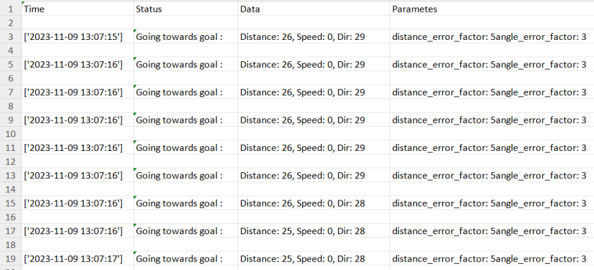
OUTPUT: By providing collection of coordinates like this we can fix the path for the fixed environment and there will be no need for any reference line as we use in line following robots.
 |
| ….……………………………………. after some time |
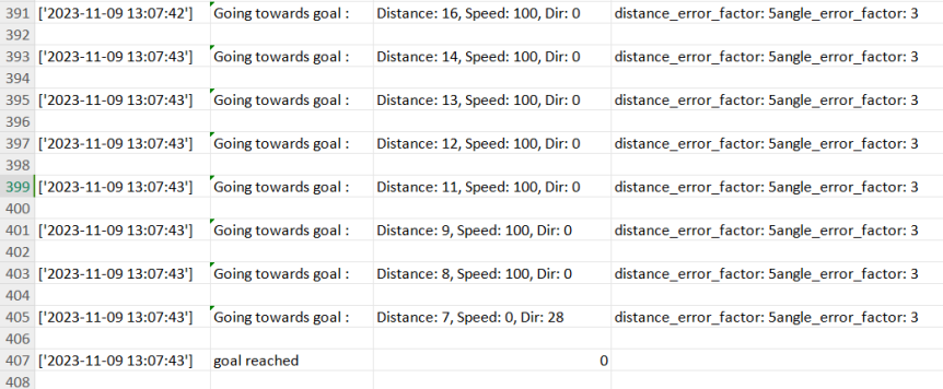 After ~30 seconds it reached its goal… |
 |
I developed this prototype bot in about a week while I was on a sprint for it, plus two extra days for embedded coding and electronics assembly. This one is special to me and still needs more work.

THANK YOU