Introduction
As always just not to forget basics I prepared this basic interesting article.
In this article, I want to explain what actually feels difficult or time consuming in development, and how and when things start to become easier. Also, why we always need to move step by step… yeah, no shortcuts here 😅
This article is based on a mini project, and I am going to talk about how to connect theory with computer programming. When I started, I always used to get stuck thinking why am I learning all this theory? How is it even important or connected to the practical cool stuff?
And yeah, because of that, I was not really interested in the theory part. But with time, I realized it is actually the backbone of everything…
There are different situations, like –
-> When you know how to rotate a motor using Arduino, STM32, ESP32, or any microcontroller.
-> And when you know how to rotate a motor using PWM, adding PID, PD, PI or any smarter approach like these.
I call things difficult when they eat up a lot of time like writing everything in code (Algo), tuning a PID, writing code for 32-bit controllers, maintaining clean and readable code, or adding features for debugging or scaling.
Yes, the real pain isn’t spinning the motor it is all the “good practices” around it
Most people can rotate a motor, but can not really explain PWM properly.
I mentioned that just to give an example because, that happened to me when I started too…
So without wasting any more time, I am going to dive into a simple implementation let’s write some basic code to rotate a motor at a defined speed so we can generate ODOM for a bot. I will be using a single motor here, just to give you a head start and a bit of exposure to how it is done.
Because if you are into robotics you have to do this 😂
Very basic stuff, and using this, you can also explore things like PID, microcontroller basics, and a whole lot more.
In this mini project, we will begin by working with an 8-bit microcontroller most likely the one you ae already familiar with: the Arduino Uno. It is simple, beginner friendly, and powerful enough for tasks like controlling motors and reading sensors. Our goal here is to control the speed of a DC motor using feedback from a rotary encoder, a small sensor that tells us how far and how fast the motor is spinning. We’ll learn how to read encoder signals, calculate speed, and even detect the direction of rotation based on the timing of two digital signals. This interaction with the encoder lays the foundation for precise motion control in robotics. Once we’re comfortable with the logic and implementation on Arduino, we will move on to more powerful 32-bit microcontrollers.
What is an Encoder?
An encoder is a tiny device that tells us how much something has rotated usually a motor shaft or a wheel. Imagine you are turning a knob or spinning a wheel, and there is a little counter keeping track of how many times you turn it. That is basically what an encoder does.
Every time the motor spins a little bit, the encoder sends small signals, called ticks, to the Arduino. By counting these ticks, we can figure out how far the motor has turned. If we count how many ticks happen in a second, we can also know how fast it’s spinning.
In this project, we’re using a type of encoder called a quadrature encoder. It has two signal wires, usually called A and B. These wires send pulses as the motor rotates. But here’s the cool part, by looking at the timing of these two signals, we can also tell which direction the motor is spinning forward or backward.
So in our code, we have connected these two encoder wires to pins 2 and 3 on the Arduino. We use something called an interrupt on one of the pins. This basically means the Arduino pays very close attention to that pin, and the moment it sees a signal, it runs a special function called readEncoder(). Inside that function, we check the second wire to see if the ticks mean “forward” or “backward,” and we update a counter (encoderTicks) accordingly.
The encoder is like the eyes of your Arduino it watches the motor and keeps reporting back how much it has moved. Without it, we would be guessing the speed. With it, we can measure the speed and make smart decisions, like speeding up or slowing down the motor automatically. That’s what makes feedback control possible.
wave signals – A and B.
They are the same frequency, but 90° out of phase.
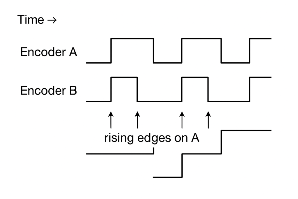
every time the signal on Encoder A rises from LOW to HIGH (called a rising edge), the signal on Encoder B can either be HIGH or LOW. Which one it is depends entirely on the direction the motor is spinning. When the motor keeps moving in a single direction, the phase difference between the two signals stays consistent. So at every rising edge of A, the value of B will always be the same either always LOW or always HIGH depending on the direction. In your code, this is exactly how direction is detected:
if (digitalRead(ENCODER_B) == LOW)
	encoderTicks++;
else
	encoderTicks--;
If the motor is rotating forward, B will always be LOW during A’s rising edge, so the tick count increases. If the motor is spinning in reverse, B will always be HIGH at that same moment, so the tick count decreases. This simple check lets your Arduino know not just how much the motor has moved, but which way it is moving.
Controlling Motor Speed Using Arduino and Encoder
In many robotics projects, we often need to move motors at a specific speed. But motors don’t always spin exactly as we expect they might go faster or slower depending on the load or power supply. That’s why we use encoders: devices that tell us how much the motor has actually turned. With this information, we can adjust the power going to the motor to keep its speed steady. This project does exactly that using Arduino.
Setting Up the Motor and Encoder Pins
At the beginning of the code, we define some pins:
const int RPWM = 5;
const int LPWM = 6;
const int R_EN = 7;
const int L_EN = 8;
These pins are connected to the motor driver, which acts like a switchboard for the motor. The RPWM and LPWM pins are used to set the motor direction and speed using something called PWM (Pulse Width Modulation). The R_EN and L_EN pins are used to enable or disable the motor. In the setup() function, we set all these pins as OUTPUT and turn the motor ON using digitalWrite().
Next, we define the encoder pins:
const int ENCODER_A = 2;
const int ENCODER_B = 3;
These pins are connected to the rotary encoder, which sends pulses (ticks) whenever the wheel rotates. This helps us measure how much the motor has turned.
We also attach an interrupt to one of the encoder pins:
attachInterrupt(digitalPinToInterrupt(ENCODER_A), readEncoder, RISING);This line means: “Every time the signal on ENCODER_A goes from LOW to HIGH, run the readEncoder() function.” This helps us count encoder ticks accurately and quickly.
Understanding Encoder Ticks and Speed Calculation
To measure speed, we need to know how far the motor has moved in a certain amount of time. Encoders help with this. We define a few constants and variables:
int encoderCPR = 330;                // Counts per revolution (can be calibrated)
const float wheelDiameter = 0.065;   // In meters
const float wheelCircumference = 3.1416 * wheelDiameter;encoderCPRmeans how many encoder pulses happen when the wheel makes one full rotation.wheelCircumferencetells us how far the wheel moves in one complete turn (calculated using the formula: π × diameter).
Measuring the Speed in the Loop
In the loop(), every 100 milliseconds, the Arduino calculates how fast the motor is moving:
unsigned long currentMillis = millis();
if (currentMillis - lastMillis >= 100) {
We check how many ticks the encoder counted during the last 100 milliseconds:
long deltaTicks = encoderTicks - lastEncoderTicks;Then we calculate how many rotations that means, and convert it into distance:
float revs = (float)deltaTicks / encoderCPR;
float distance = revs * wheelCircumference;
Finally, speed is distance divided by time. Since we check every 0.1 seconds (100 milliseconds), we write:
currentSpeed = distance / 0.1; // in meters per secondThis gives us the real-time speed of the motor in meters per second.
Reaching the Target Speed (P-Control)
Now we want to make the motor spin at the speed we choose. For example, if we want it to spin at 0.3 m/s, we need to increase or decrease power until it reaches that speed.
We calculate the error like this:
float error = targetSpeed - currentSpeed;We then multiply that error by a constant Kp to get a new PWM value:
float Kp = 300;
pwmValue += Kp * error;
This method is called Proportional Control (P-Control). If the motor is going too slow, the PWM increases. If it’s too fast, it decreases. The goal is to make the error as small as possible. We also use constrain() to make sure the PWM stays between 0 and 255:
pwmValue = constrain(pwmValue, 0, 255);Finally, we send this PWM value to the motor using:
driveMotor(pwmValue);This function sets RPWM to the PWM value and turns off LPWM, which makes the motor go forward.
Changing Speed Using Serial Monitor
In the loop(), we also listen for user input from the Serial Monitor:
if (Serial.available()) {
  String input = Serial.readStringUntil('\n');
If you type a number like 0.3, the program sets that as the new target speed. If you type 'c', it starts the encoder calibration process.
Encoder Calibration
Sometimes, your encoder might have a different number of ticks per wheel turn than expected. That’s why the code includes a helper function:
void calculateEncoderCPR() {
  encoderTicks = 0;
  Serial.println("Rotate wheel 1 full turn by hand...");
  delay(5000);
  int countedTicks = encoderTicks;
This resets the encoder count and waits for 5 seconds so you can turn the wheel once. It then prints how many ticks it counted during one full rotation. You can use that number to update encoderCPR for more accurate speed measurement.
This is a great starting point for controlling the speed of a motor using feedback from an encoder. By using P-control, we can make sure the motor maintains a steady speed, even if the load or power supply changes. This kind of control is useful in many real-world machines, like robots, conveyors, and even 3D printers.
You can improve this project by adding full PID control (Proportional–Integral–Derivative), controlling motor direction, or controlling two motors at once. But even with this basic version, you’re already doing real-world motor speed control using Arduino!
CODE:
const int RPWM = 5;
const int LPWM = 6;
const int R_EN = 7;
const int L_EN = 8;

const int ENCODER_A = 2;
const int ENCODER_B = 3;

volatile long encoderTicks = 0;
long lastEncoderTicks = 0;
unsigned long lastMillis = 0;

int encoderCPR = 330;                // Can be changed using calibration
const float wheelDiameter = 0.065;   // meters
const float wheelCircumference = 3.1416 * wheelDiameter;

float targetSpeed = 0.0;    // m/s
float currentSpeed = 0.0;   // m/s
int pwmValue = 0;           // PWM output

void setup() {
  Serial.begin(9600);

  pinMode(RPWM, OUTPUT);
  pinMode(LPWM, OUTPUT);
  pinMode(R_EN, OUTPUT);
  pinMode(L_EN, OUTPUT);
  digitalWrite(R_EN, HIGH);
  digitalWrite(L_EN, HIGH);

  pinMode(ENCODER_A, INPUT_PULLUP);
  pinMode(ENCODER_B, INPUT_PULLUP);
  attachInterrupt(digitalPinToInterrupt(ENCODER_A), readEncoder, RISING);

  Serial.println("Ready. Send target speed in m/s (e.g. 0.3).");
  Serial.println("Send 'c' to calculate encoder CPR manually.");
}

void loop() {
  unsigned long currentMillis = millis();


  if (currentMillis - lastMillis >= 100) {
    long deltaTicks = encoderTicks - lastEncoderTicks;
    lastEncoderTicks = encoderTicks;

    float revs = (float)deltaTicks / encoderCPR;
    float distance = revs * wheelCircumference;
    currentSpeed = distance / 0.1;  // in m/s

    float error = targetSpeed - currentSpeed;
    float Kp = 300; // Tune as needed
    pwmValue += Kp * error;
    pwmValue = constrain(pwmValue, 0, 255);
    driveMotor(pwmValue);

    Serial.print("Target: ");
    Serial.print(targetSpeed);
    Serial.print(" m/s | Current: ");
    Serial.print(currentSpeed);
    Serial.print(" m/s | PWM: ");
    Serial.println(pwmValue);

    lastMillis = currentMillis;
  }


  if (Serial.available()) {
    String input = Serial.readStringUntil('\n');
    input.trim();

    if (input == "c") {
      calculateEncoderCPR();
    } else {
      float spd = input.toFloat();
      if (spd >= 0.0) {
        targetSpeed = spd;
        Serial.print("Set target speed to: ");
        Serial.print(targetSpeed);
        Serial.println(" m/s");
      }
    }
  }
  Serial.print("Ticks: ");
Serial.println(encoderTicks);
}


void readEncoder() {
  if (digitalRead(ENCODER_B) == LOW)
    encoderTicks++;
  else
    encoderTicks--;
}

void driveMotor(int pwm) {
  analogWrite(RPWM, pwm);
  analogWrite(LPWM, 0); // Forward only
}

void calculateEncoderCPR() {
  encoderTicks = 0;
  Serial.println("Rotate wheel 1 full turn by hand...");
  delay(5000);
  noInterrupts();
  int countedTicks = encoderTicks;
  interrupts();
  Serial.print("Measured CPR: ");
  Serial.println(countedTicks);
  Serial.println("Update 'encoderCPR' in code to this value.");
}
Lets continue with 32-bit microcontroller
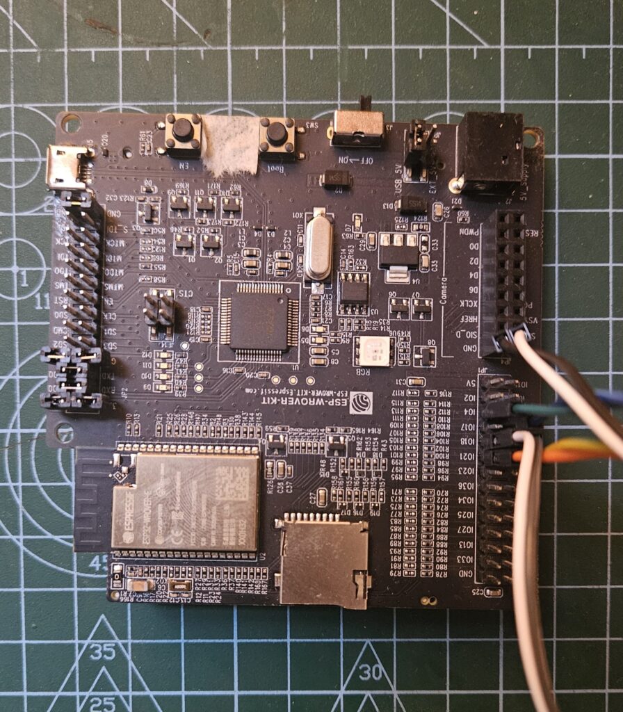
The ESP32-WROVER-E is a powerful and versatile Wi-Fi and Bluetooth module developed by Espressif Systems, built around the ESP32-D0WDQ6 chip. It features a dual-core 32-bit processor with clock speeds up to 240 MHz, making it suitable for demanding IoT, automation, and embedded applications. The WROVER-E stands out by including 4 MB of Flash and 8 MB of PSRAM, providing ample memory for complex applications like image processing, machine learning, or real-time communication. It supports Wi-Fi (802.11 b/g/n) and Bluetooth 4.2 BR/EDR and BLE, and includes a wide range of peripherals such as SPI, I2C, UART, PWM, ADC, DAC, and more. The module comes in variants with either PCB antenna or an external IPEX antenna connector. Its robust feature set and large memory make the ESP32-WROVER-E ideal for advanced IoT solutions, edge computing, and applications involving camera modules, sensors, and real-time data processing.
Refer this for getting started with documentation :
https://docs.espressif.com/projects/esp-idf/en/stable/esp32/api-reference/index.html#
For devkit :
https://docs.espressif.com/projects/esp-dev-kits/en/latest/esp32/esp-wrover-kit/user_guide.html
Lets breakdown the code of ESP32 and get some understanding how it is different from Arduino.
Like in this algo is same, but there are a few things which you should know first…
PWM (MCPWM)
PWM (Pulse Width Modulation) is used to control how much power is delivered to the motor. The MCPWM (Motor Control PWM) module in ESP32 generates PWM signals to vary motor speed by changing the duty cycle (percentage of ON time in one cycle). For more information, scroll to the bottom of this article.
PCNT (Pulse Counter)
The PCNT module counts the number of electrical pulses from the encoder. Each pulse represents a small movement of the wheel, allowing the system to measure how fast or how far the motor has turned.
PID Control
PID (Proportional–Integral–Derivative) is a control algorithm that adjusts the motor’s speed. It compares the target speed (input) with the measured speed (from encoder), and changes the PWM to reduce the difference (error) over time.
UART
UART (Universal Asynchronous Receiver-Transmitter) is a serial communication protocol. Here, it is used to receive the desired speed (as text/number) from a user via a computer or app.
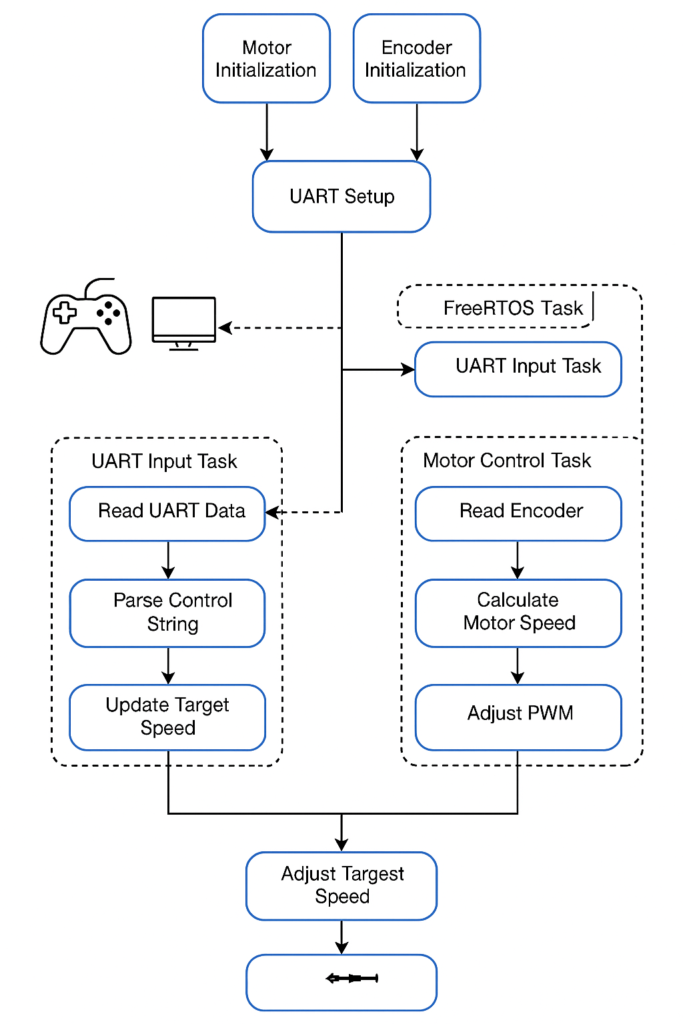
FreeRTOS Tasks
FreeRTOS allows the program to run multiple tasks at the same time. In this code, one task handles UART communication and another task continuously adjusts motor speed using PID control.
ESP_LOGI
A logging function provided by the ESP32 framework to print debug or status messages (e.g., speed, PWM value) to the serial monitor for real-time observation.
FLOW DIAGRAM
CODE:
#include <stdio.h>
#include <string.h>
#include "freertos/FreeRTOS.h"
#include "freertos/task.h"
#include "driver/gpio.h"
#include "driver/mcpwm.h"
#include "driver/pcnt.h"
#include "driver/uart.h"
#include "esp_log.h"

#define TAG_MOTOR   "MOTOR"
#define TAG_ENCODER "ENCODER"
#define TAG_UART    "UART"


#define RPWM_GPIO   4
#define LPWM_GPIO   5
#define R_EN_GPIO   21
#define L_EN_GPIO   22


#define PCNT_INPUT_SIG_IO   18
#define PCNT_INPUT_CTRL_IO  19
#define PCNT_UNIT           PCNT_UNIT_0


#define ENCODER_CPR         600
#define WHEEL_DIAMETER_M    0.065
#define SAMPLE_INTERVAL_MS  100   // 100 ms control loop


#define UART_RX_BUF_SIZE    1024


static volatile float target_speed_mps = 0.0;
static float measured_speed_mps = 0.0;
static float control_output_pwm = 0.0;


float Kp = 80.0;
float Ki = 20.0;
float Kd = 5.0;


float integral = 0.0;
float prev_error = 0.0;


void motor_init(void)
{
    gpio_set_direction(R_EN_GPIO, GPIO_MODE_OUTPUT);
    gpio_set_direction(L_EN_GPIO, GPIO_MODE_OUTPUT);
    gpio_set_level(R_EN_GPIO, 1);
    gpio_set_level(L_EN_GPIO, 1);

    mcpwm_gpio_init(MCPWM_UNIT_0, MCPWM0A, RPWM_GPIO);
    mcpwm_gpio_init(MCPWM_UNIT_0, MCPWM0B, LPWM_GPIO);

    mcpwm_config_t pwm_config = {
        .frequency = 1000,
        .cmpr_a = 0.0,
        .cmpr_b = 0.0,
        .counter_mode = MCPWM_UP_COUNTER,
        .duty_mode = MCPWM_DUTY_MODE_0
    };
    mcpwm_init(MCPWM_UNIT_0, MCPWM_TIMER_0, &pwm_config);
}

void motor_apply_pwm(float duty)
{
    if (duty < 0) duty = 0;
    if (duty > 100) duty = 100;

    mcpwm_set_duty(MCPWM_UNIT_0, MCPWM_TIMER_0, MCPWM_OPR_A, duty);
    mcpwm_set_duty(MCPWM_UNIT_0, MCPWM_TIMER_0, MCPWM_OPR_B, 0);
}


void encoder_init(void)
{
    pcnt_config_t pcnt_config = {
        .pulse_gpio_num = PCNT_INPUT_SIG_IO,
        .ctrl_gpio_num = PCNT_INPUT_CTRL_IO,
        .channel = PCNT_CHANNEL_0,
        .unit = PCNT_UNIT,
        .pos_mode = PCNT_COUNT_INC,
        .neg_mode = PCNT_COUNT_DIS,
        .lctrl_mode = PCNT_MODE_REVERSE,
        .hctrl_mode = PCNT_MODE_KEEP,
        .counter_h_lim = 10000,
        .counter_l_lim = -10000,
    };

    pcnt_unit_config(&pcnt_config);
    pcnt_set_filter_value(PCNT_UNIT, 100);
    pcnt_filter_enable(PCNT_UNIT);
    pcnt_counter_clear(PCNT_UNIT);
    pcnt_counter_resume(PCNT_UNIT);
}


void uart_init()
{
    uart_config_t uart_config = {
        .baud_rate = 115200,
        .data_bits = UART_DATA_8_BITS,
        .parity    = UART_PARITY_DISABLE,
        .stop_bits = UART_STOP_BITS_1,
        .flow_ctrl = UART_HW_FLOWCTRL_DISABLE
    };

    uart_param_config(UART_NUM_0, &uart_config);
    uart_driver_install(UART_NUM_0, UART_RX_BUF_SIZE * 2, 0, 0, NULL, 0);
}

void uart_read_task(void *arg)
{
    uint8_t data[32];
    while (1) {
        int len = uart_read_bytes(UART_NUM_0, data, sizeof(data) - 1, pdMS_TO_TICKS(100));
        if (len > 0) {
            data[len] = '\0';
            float input_speed = atof((char *)data);
            if (input_speed >= 0 && input_speed <= 1.5) {
                target_speed_mps = input_speed;
                ESP_LOGI(TAG_UART, "New Target Speed: %.2f m/s", target_speed_mps);
            }
        }
    }
}


void pid_control_task(void *arg)
{
    int16_t prev_count = 0, curr_count = 0, delta = 0;
    float dt = SAMPLE_INTERVAL_MS / 1000.0f;
    const float wheel_circumference = WHEEL_DIAMETER_M * 3.14159;
    float pwmValue = 0.0;
    const float Kp = 300.0;  // Tune as needed

    while (1) {

        pcnt_get_counter_value(PCNT_UNIT, &curr_count);
        delta = curr_count - prev_count;
        prev_count = curr_count;


        float currentSpeed = ((float)delta / ENCODER_CPR) * wheel_circumference / dt;
        measured_speed_mps = currentSpeed;


        float error = target_speed_mps - currentSpeed;
        pwmValue += Kp * error;


        if (pwmValue < 0.0) pwmValue = 0.0;
        if (pwmValue > 100.0) pwmValue = 100.0;


        motor_apply_pwm(pwmValue);

        ESP_LOGI(TAG_ENCODER, "Speed: %.3f m/s | Target: %.3f | PWM: %.1f%%", currentSpeed, target_speed_mps, pwmValue);

        vTaskDelay(pdMS_TO_TICKS(SAMPLE_INTERVAL_MS));
    }
}


void app_main(void)
{
    motor_init();
    encoder_init();
    uart_init();

    xTaskCreate(uart_read_task, "uart_read_task", 2048, NULL, 5, NULL); // RTOS tasks
    xTaskCreate(pid_control_task, "pid_control_task", 4096, NULL, 5, NULL); // RTOS tasks
}
Result
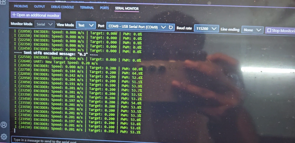
| Snip_1: As you can see in this 0.2 m/s sent to the controller and motor archived that speed with ~53% of PWM it took few milli seconds to get stable… |
 |
And about PWM
PWM, or Pulse Width Modulation, is a technique used to control the amount of power delivered to electronic devices by rapidly switching the power on and off. The idea is that by adjusting how long the signal stays on compared to how long it stays off in each cycle, you can control how much power the device receives. This ratio is called the duty cycle. A higher duty cycle means the signal is on for more time, so the device receives more power. For example, a 100% duty cycle means the power is always on, while a 50% duty cycle means it is on half the time. PWM is commonly used in applications such as motor speed control, LED brightness control, servo motor positioning, and sound generation.
PWM controls motor speed by rapidly turning the motor’s power supply on and off at a high frequency. The speed control lies in the duty cycle, which is the percentage of time the signal stays on during each cycle.
-> When the PWM signal has a high duty cycle (for example, 80%), the motor receives power for most of the time, so it runs faster.
-> When the duty cycle is low (say, 20%), the motor gets power only briefly in each cycle, so it runs slower.
Even though the power is being turned on and off, this happens so fast (thousands of times per second) that the motor doesn’t stop and start each time it simply averages out the power and runs at a speed proportional to that average.
— THANK YOU —
Perfect article for revising basic motor code. I am always inspired by your projects. Very well done!
Thank you very much Riya !